Real-time IoT dashboards with Arduino and Azure offer a powerful way to monitor and analyze data from connected devices. These dashboards give users instant access to important information from sensors and other IoT devices. With Arduino boards and Azure cloud services, you can build a system that collects data and displays it on a live dashboard.
Setting up this type of IoT system involves a few key steps. First, you need to connect your Arduino device to Azure IoT Hub. This allows your device to send data securely to the cloud. Next, you’ll need to set up a way to process and store the incoming data. Finally, you’ll create a web app or dashboard to show the data in real-time.
One benefit of using Azure for IoT projects is its built-in tools for data visualization. These tools make it easier to create dashboards without having to build everything from scratch. Azure also offers features for analyzing large amounts of IoT data, which can help uncover useful insights from your connected devices.
Building Your Own IoT Dashboard
What You’ll Need
To create a real-time IoT dashboard with Arduino and Azure, you’ll need a few things:
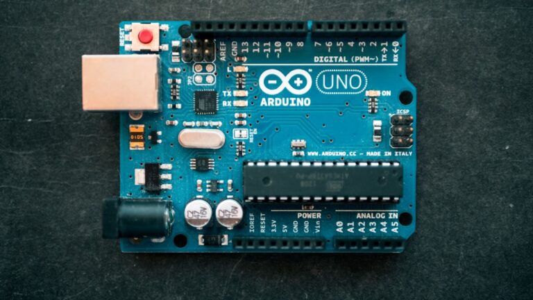
- An Arduino board: This will be the brain of your IoT project. Popular choices include the Arduino Uno, Nano, or Mega.
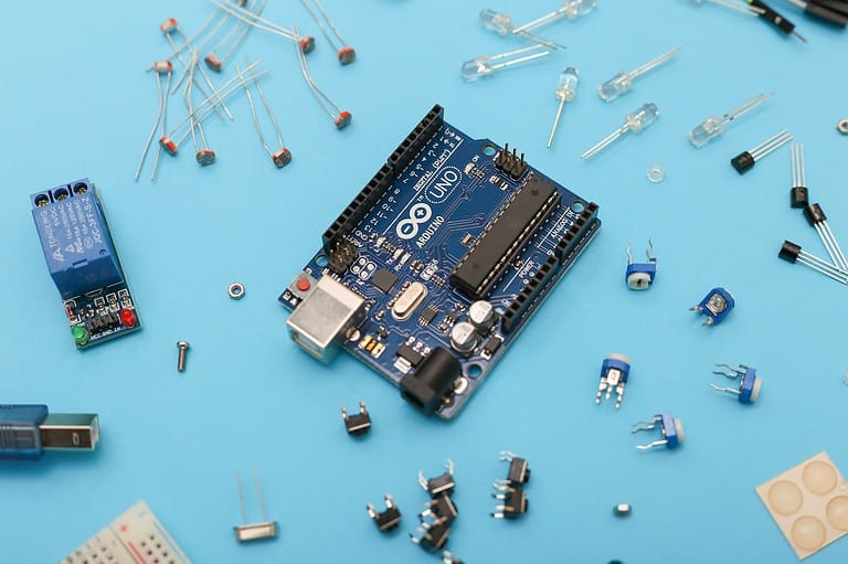
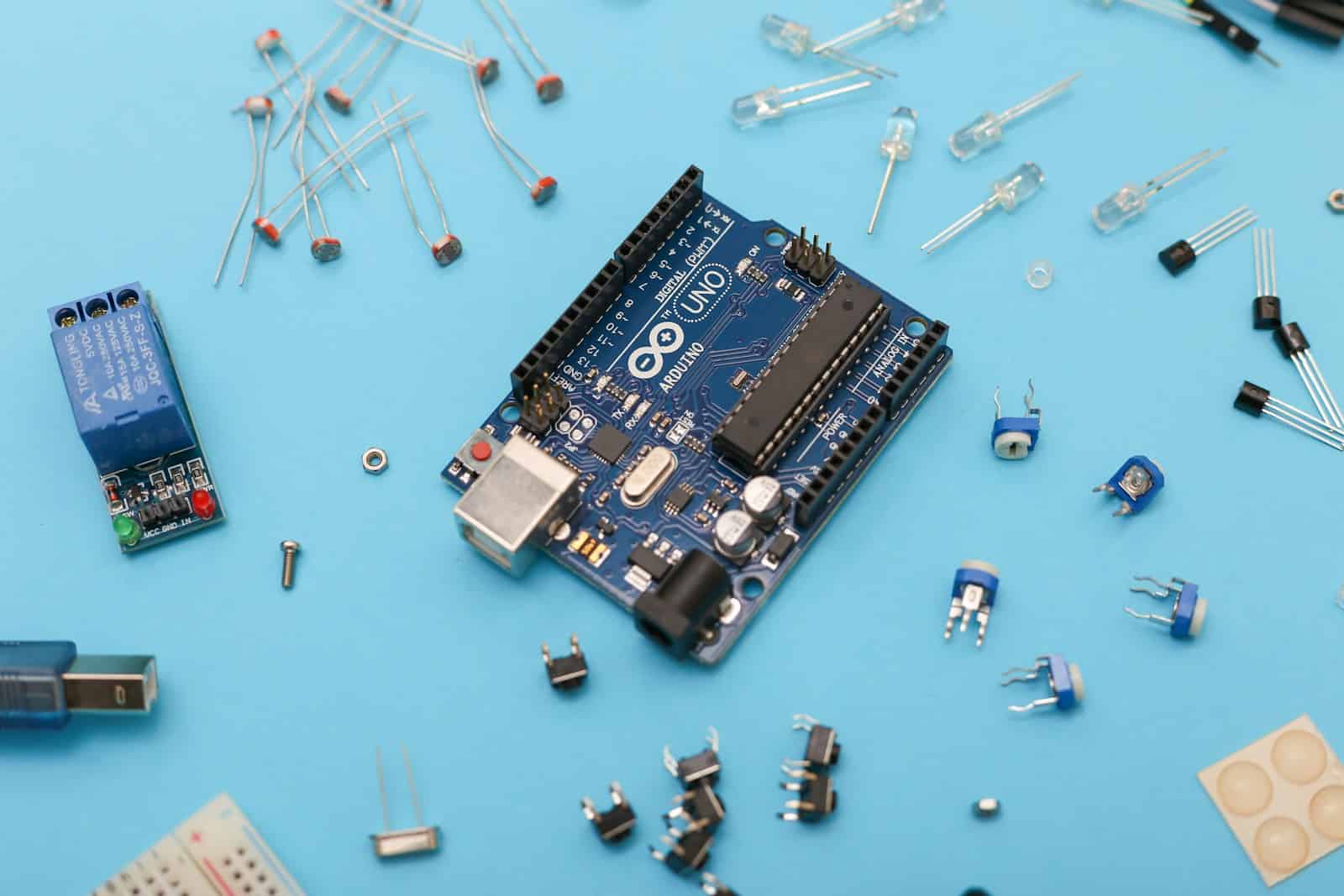
- Sensors: Choose sensors that are relevant to the data you want to collect. This could include temperature sensors, humidity sensors, pressure sensors, or even GPS modules.
- An internet connection: You’ll need an internet connection to send data from your Arduino to Azure.
- An Azure subscription: You can sign up for a free trial of Azure to get started.
- Software: You’ll need the Arduino IDE to program your Arduino board and a web browser to access the Azure portal.
Setting Up Your Arduino
The first step is to connect your sensors to your Arduino board. You can find wiring diagrams and code examples online for various sensors. Once your sensors are connected, you’ll need to write a program that reads data from the sensors and sends it to Azure.
Connecting to Azure
Azure offers several services that you can use to build your IoT dashboard. One popular option is Azure IoT Hub. This service allows you to securely connect and manage your IoT devices. You can use the Azure portal to create an IoT hub and register your Arduino device.
Creating Your Dashboard
Once your Arduino is sending data to Azure, you can create a dashboard to visualize that data. Azure provides a service called Azure Dashboard that allows you to create custom dashboards with various charts and graphs. You can also use other tools, such as Power BI, to create more advanced dashboards.
Visualizing Your Data
You can use a variety of visualizations to display your IoT data, including:
- Line charts: Show trends over time
- Bar charts: Compare different data points
- Gauges: Display real-time values
- Maps: Show the location of your devices
Example Project: Temperature Monitoring
Let’s say you want to build a real-time temperature monitoring system. You could use a temperature sensor connected to your Arduino to collect temperature data. This data could then be sent to Azure IoT Hub and visualized on an Azure Dashboard. You could create a line chart to show temperature trends over time, or a gauge to display the current temperature.
Extending Your Project
Once you’ve built your basic IoT dashboard, you can extend it with additional features. For example, you could add alerts that notify you if the temperature exceeds a certain threshold. You could also use machine learning to predict future temperature trends.
| Component | Purpose | Example |
|---|---|---|
| Arduino Board | Collects data from sensors | Arduino Uno, Nano, Mega |
| Sensors | Measure physical quantities | Temperature, humidity, pressure, GPS |
| Azure IoT Hub | Securely connect and manage devices | – |
| Azure Dashboard | Visualize data | Line charts, bar charts, gauges, maps |
Key Takeaways
- Arduino and Azure combine to create real-time IoT dashboards
- Secure data transmission is crucial for IoT projects
- Azure provides tools for data storage, processing, and visualization
Building the IoT Solution with Arduino and Azure
Creating an IoT solution with Arduino and Azure involves picking hardware, connecting to the cloud, and writing code. These steps help build a system that can gather and analyze data from devices.
Selecting the Right Hardware
Arduino offers many boards for IoT projects. The ESP8266 and ESP32 are popular choices. They have built-in Wi-Fi, making them ideal for IoT.
The ESP8266 is low-cost and works well for simple projects. The ESP32 has more power and features. It’s better for complex tasks.
For bigger projects, developers might use a Raspberry Pi. It can handle more data and run more complex software.
When picking hardware, consider:
- Power needs
- Size limits
- Data processing needs
- Cost
Establishing Cloud Connectivity
Azure IoT Hub is key for cloud connectivity. It’s a service that lets devices talk to the cloud safely.
To connect a device:
- Make an IoT Hub in Azure
- Register the device
- Get a device connection string
The device connection string is like a password. It lets the device join the IoT Hub.
MQTT is a common way for devices to send data. It’s light and fast, perfect for IoT.
Wi-Fi is often used to connect devices to the internet. Make sure to pick hardware with good Wi-Fi support.
Programming with Arduino IDE
The Arduino IDE makes coding for IoT devices easy. It works with many boards, including ESP8266 and ESP32.
To start:
- Install the Arduino IDE
- Add board support for ESP8266/ESP32
- Install the Azure IoT SDK library
The Azure IoT SDK helps connect to Azure services. It handles tasks like sending messages and managing connections.
Code structure in Arduino IDE:
- setup(): Runs once when the device starts
- loop(): Runs over and over
In setup(), connect to Wi-Fi and Azure. In loop(), read sensors and send data.
Sample code often comes with libraries. These show how to use different features.
Data Handling and Analysis
Managing IoT data involves collecting sensor info and turning it into useful insights. This process includes handling telemetry data, showing it in real-time, and using tools to make sense of the information.
Telemetry Data Management
Telemetry data from IoT devices is key for tracking and improving systems. The Azure SDK for C helps connect Arduino boards to Azure IoT Hub. It allows sending data from sensors to the cloud.
To set up data flow:
- Install the Azure SDK for C in Arduino IDE
- Connect the Arduino to Wi-Fi
- Set up Azure IoT Hub credentials
- Use MQTT protocol to send messages
The PubSubClient library can help with MQTT messaging. It’s simple to use and works well with Arduino.
Real-Time Data Visualization
Seeing data as it comes in helps spot trends quickly. Power BI is a tool that can make live dashboards for IoT data.
Steps to create a real-time view:
• Connect Power BI to your data source
• Pick the right chart types
• Set up auto-refresh
Azure Data Explorer also works well for looking at IoT info. It can handle lots of data and make charts fast.
Using these tools lets teams see what’s happening with machines right away. This quick view helps fix problems before they get big.
Leveraging Stream Analytics
Azure Stream Analytics helps process IoT data as it comes in. It can spot patterns and trigger actions based on the data.
Some ways to use Stream Analytics:
• Find average sensor readings over time
• Trigger alerts when values pass a limit
• Clean up messy data
Stream Analytics can work with machine learning models too. This combo can predict when machines might break down.
For bigger projects, Azure Event Hub can take in more data. It works well with Stream Analytics for large-scale IoT setups.
Frequently Asked Questions
Creating a real-time IoT dashboard with Arduino and Azure involves several key steps. These include setting up the Arduino device, connecting it to Azure IoT Hub, sending data, and visualizing it in a dashboard.
How can one create a real-time IoT dashboard using Arduino and Azure?
To make a real-time IoT dashboard with Arduino and Azure, start by setting up an Arduino board with sensors. Next, create an Azure account and set up IoT Hub. Then, connect the Arduino to Azure IoT Hub. Finally, use Azure services like Stream Analytics to process data and Power BI to create a dashboard.
What are the steps to connect an Arduino device to Azure IoT Hub?
First, install the Arduino library for Azure IoT in the Arduino IDE. Next, set up an IoT Hub in Azure and register your Arduino device. Then, add the connection string to your Arduino code. Last, upload the code to your Arduino board to establish the connection.
How does sending telemetry data from Arduino to Azure IoT Hub work?
Arduino devices send telemetry data to Azure IoT Hub using the MQTT protocol. The Arduino code reads sensor data and formats it as JSON. It then sends this data to IoT Hub at set times. IoT Hub receives and stores the data for further processing or analysis.
What are the requirements for integrating Arduino with Azure IoT services?
To integrate Arduino with Azure IoT services, you need:
- An Arduino board with internet access
- Azure account and IoT Hub set up
- Arduino IDE with Azure IoT library installed
- Basic coding skills in C++ and JSON
How to visualize IoT data from Arduino in an Azure dashboard?
To show Arduino IoT data in an Azure dashboard:
- Set up Stream Analytics to process data from IoT Hub
- Create a Power BI workspace
- Connect Stream Analytics output to Power BI
- Design charts and graphs in Power BI using the IoT data
- Publish the dashboard for real-time viewing
What examples are there of Arduino-based projects using Azure for real-time dashboard applications?
Arduino-Azure projects with real-time dashboards include:
- Home weather stations that track temperature and humidity
- Smart agriculture systems monitoring soil moisture and light levels
- Industrial machine monitoring for predictive maintenance
- Smart city applications tracking air quality and noise levels
These projects use Arduino to collect data and Azure to process and display it in real-time dashboards.