A multimeter is one of the most important tools for anyone interested in electronics or home repairs. This versatile device can measure voltage, current, resistance, and more – helping you diagnose problems in electrical circuits and devices. Learning how to properly use a multimeter can save you hundreds of dollars in repair costs and prevent dangerous electrical accidents.
Getting started with a multimeter might seem intimidating at first glance with all those dials, settings, and probes. But don’t worry – using a multimeter is simpler than it looks. Whether you need to check if a battery still has charge, find a break in a wire, or troubleshoot a malfunctioning appliance, this essential tool provides clear answers about electrical problems.
Safety should always come first when working with electricity. Always handle your multimeter correctly by using the proper probe connections and settings for each measurement. With some basic knowledge and practice, anyone can become proficient in using this valuable diagnostic tool.
How to Use a Multimeter: Step-by-Step Guide
A multimeter is one of the most useful tools for anyone working with electronics, electrical systems, or DIY repairs. It measures voltage, current, resistance, and continuity — helping you test batteries, outlets, fuses, and circuits safely.
🧰 What You’ll Need
- A digital multimeter (DMM)
- Two test probes (red = positive, black = negative)
- The device or circuit you want to test
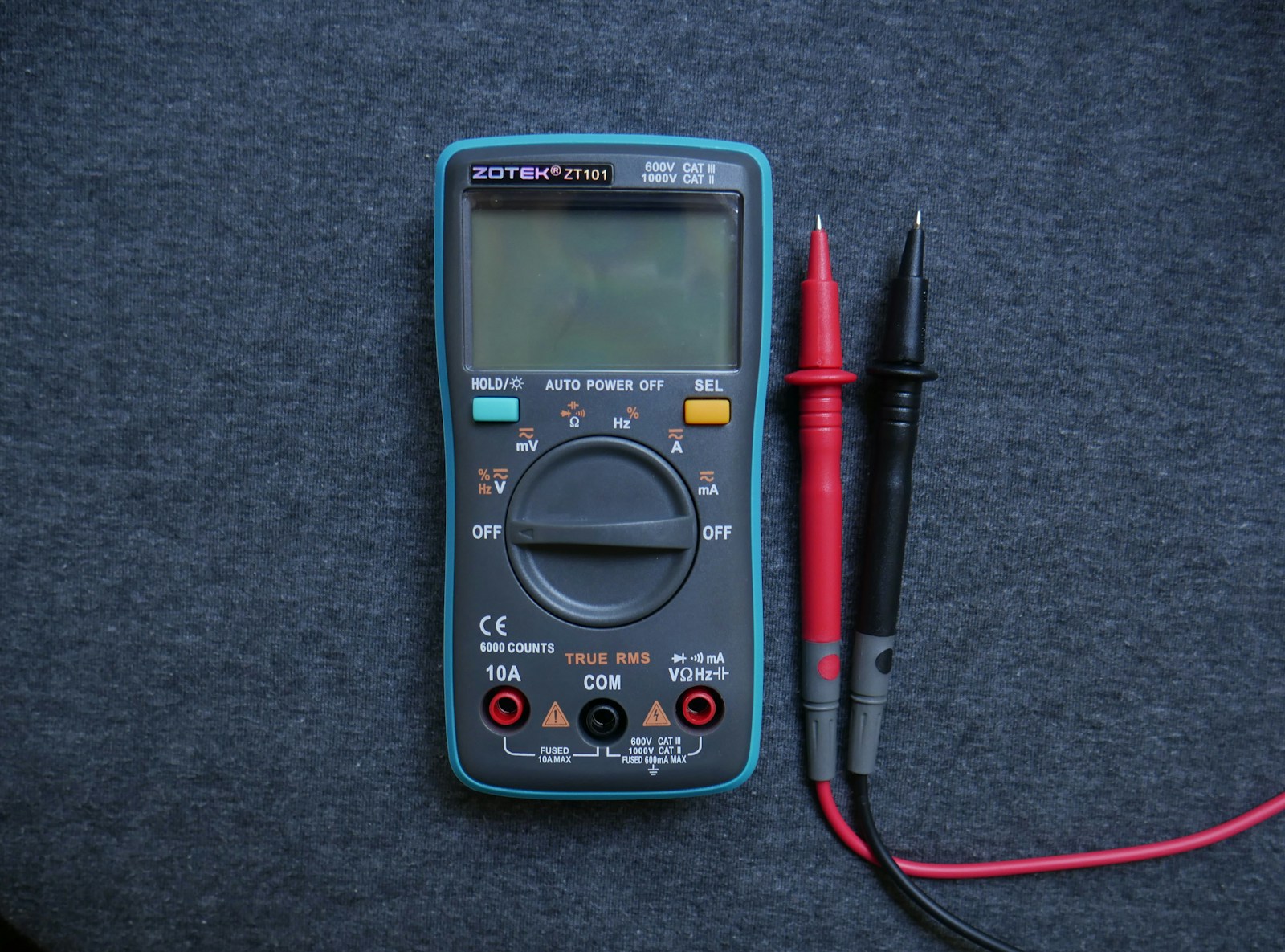
⚙️ Step 1: Understand Your Multimeter
Before using it, get familiar with the main parts:
| Part | Function |
|---|---|
| Display | Shows readings (volts, amps, ohms, etc.) |
| Dial/Selector | Lets you choose what to measure |
| Ports | Where you plug in the test leads |
| Test Leads | Red = positive, Black = negative |
Common port labels:
- COM → Common (always for black lead)
- VΩmA → For measuring voltage, resistance, and small currents
- 10A → For measuring high current (up to 10 amps)
⚡ Step 2: Safety First
- Make sure your hands are dry.
- Never measure resistance or continuity on a powered circuit.
- Always start with the highest range on manual multimeters to avoid overload.
- Check that your test leads are in the correct ports.
🔋 Step 3: Measure Voltage (AC/DC)
🧭 To measure DC voltage (batteries, electronics):
- Turn the dial to V⎓ (DC voltage).
- Plug the black lead into COM, and red lead into VΩmA.
- Touch the black probe to the negative terminal, red probe to the positive.
- Read the value on the screen.
✅ Example: A healthy AA battery should read around 1.5V.
⚡ To measure AC voltage (wall outlets):
- Turn the dial to V~ (AC voltage).
- Insert the probes into the two outlet slots.
- Read the voltage — in most regions, it should be around 110–120V (US) or 220–240V (EU).
⚠️ Caution: Be careful when testing live outlets — don’t touch the metal probe tips.
🔄 Step 4: Measure Resistance (Ω)
- Turn the dial to the Ω (ohm) symbol.
- Touch the probes to both ends of the component (e.g., resistor, wire).
- Read the resistance.
- A low number = good conductor.
- “OL” or infinity (∞) = open circuit or broken connection.
✅ Example: A 220Ω resistor should read close to 220 ohms.
💡 Step 5: Test Continuity (Beep Mode)
Continuity checks if electricity can flow through a circuit — perfect for checking fuses or wires.
- Turn the dial to the continuity setting (🔔 or diode symbol).
- Touch the probes to both ends of the wire or component.
- If the multimeter beeps, the circuit is continuous (good).
- No beep = broken or disconnected wire.
🔌 Step 6: Measure Current (Amps)
⚠️ Important: Measuring current requires breaking the circuit — electricity must flow through the multimeter.
- Move the red lead to the 10A port (for high current).
- Turn the dial to A⎓ (DC current) or A~ (AC current).
- Connect the multimeter in series with your circuit (not across).
- Read the current value.
✅ Example: A smartphone charger might draw 1–2 amps.
🧠 Step 7: Optional — Test Diodes or Capacitors
To test a diode:
- Select the diode (→|–) setting.
- Touch the red probe to the anode (+) and black to the cathode (–).
- A good diode shows a small voltage drop (~0.6V).
- Reverse the probes — should show OL (no current flow).
To test a capacitor (on advanced meters):
- Select the capacitance (F) setting.
- Discharge the capacitor first.
- Connect probes and read the capacitance value.
🧾 Step 8: Interpret Your Readings
| Symbol | Measurement | Typical Range |
|---|---|---|
| V~ | AC Voltage | 110–240V |
| V⎓ | DC Voltage | 1.5–24V |
| Ω | Resistance | 0–1MΩ |
| A⎓ / A~ | Current | mA–10A |
| 🔔 | Continuity | Beep = Good connection |
🧩 Step 9: Turn Off and Store Properly
- Turn the dial to OFF when done.
- Remove the test leads.
- Store your multimeter in a dry, clean place.
- Replace the battery periodically.
✅ Quick Reference Summary
| Task | Setting | Connection Type |
|---|---|---|
| Check battery | V⎓ | Parallel |
| Check wall outlet | V~ | Parallel |
| Test resistor | Ω | Parallel |
| Check wire continuity | 🔔 | Parallel |
| Measure current | A⎓ / A~ | Series |
🧰 Recommended Beginner Multimeters (2025)
| Model | Type | Price | Best For |
|---|---|---|---|
| Fluke 101 | Digital | $45 | Reliable everyday use |
| Klein Tools MM400 | Digital | $60 | DIY & home repairs |
| AstroAI 6000 | Digital | $30 | Budget-friendly starter |
| Fluke 117 | Digital | $200 | Professional-grade accuracy |
🏁 Final Thoughts
A multimeter is an essential tool for diagnosing electrical problems safely and accurately. Once you learn the basics — voltage, resistance, and continuity — you can troubleshoot almost any circuit with confidence.
Key Takeaways
- A multimeter measures voltage, current and resistance, allowing users to diagnose electrical problems safely.
- Different measurements require specific settings and probe connections on the multimeter to avoid damage to the device or electrical shock.
- Regular practice with a multimeter on simple circuits builds confidence and helps develop troubleshooting skills for more complex electrical issues.
Understanding Multimeter Basics
A multimeter is an essential tool for electronics work that measures multiple electrical values. This versatile device helps you troubleshoot circuits by measuring voltage, current, resistance, and continuity.
Parts of a Multimeter
Most multimeters consist of four main components: the display, selection knob, ports, and probes. The display shows measurement readings, typically with 3-4 digits and sometimes additional indicators. Modern digital multimeters use LCD screens that are easy to read in various lighting conditions.
The ports are the connection points where test leads plug in. Common ports include:
- COM (Common/Ground) – Black probe always connects here
- VΩmA – For voltage, resistance, and low current measurements
- 10A – For high current measurements (usually up to 10 amps)
The probes (or test leads) connect to the ports and make contact with the circuit being tested. They typically have insulated handles with metal tips and come in red (positive) and black (negative) colors for proper polarity identification.
Multimeter Symbols and Selection Knob
The selection knob is the dial you turn to choose what you want to measure. Common symbols on the knob include:
| Symbol | Measurement | Typical Units |
|---|---|---|
| V~ or ACV | AC Voltage | Volts (V) |
| V⎓ or DCV | DC Voltage | Volts (V) |
| A | Current | Amps (A) |
| Ω | Resistance | Ohms (Ω) |
| ))) | Continuity | Beep indicates connection |
| hFE | Transistor test | Gain value |
| Hz | Frequency | Hertz (Hz) |
Many multimeters also have multiple ranges for each measurement type. For example, voltage settings might include 200mV, 2V, 20V, 200V, and 1000V. Always select a range higher than what you expect to measure.
Digital vs. Analog Multimeters
Digital multimeters (DMMs) are the most common today. They provide precise numerical readings on LCD screens and often include additional features like auto-ranging, which automatically selects the appropriate measurement range. DMMs are generally more accurate and easier to read than their analog counterparts.
Analog multimeters use a moving needle to display readings. While less common now, some technicians prefer them for observing gradually changing values or trends. Analog models typically require manual range selection and more interpretation skill.
One key advantage of digital models is their higher input impedance, which means they draw less current from the circuit being tested, resulting in more accurate measurements. Modern digital multimeters also often include advanced features like data hold, min/max recording, and backlit displays.
Safety and Preparation Tips
Working with electricity requires proper safety precautions. Always follow these guidelines:
- Inspect your multimeter and probes for damage before use
- Never measure current on a high-voltage circuit
- Use one hand when possible to avoid creating a path for current through your heart
- Wear insulated gloves when working with voltages above 50V
- Never use a multimeter with voltage ratings lower than your circuit
Before testing, ensure the multimeter is set to the correct measurement type and range. For voltage measurements, connect the multimeter in parallel with the component. For current, you must connect it in series.
Always start with the highest range setting when measuring unknown values and work your way down. This protects both you and the multimeter from unexpected high readings.
Setting Up Your Multimeter
Before taking any measurements, you need to properly set up your multimeter. This involves installing a fresh battery and correctly connecting the test probes to the appropriate ports.
Installing the Battery
Most digital multimeters require a 9-volt battery, though some models may use AA or AAA batteries. To install the battery:
- Locate the battery compartment on the back of your multimeter
- Remove the cover (usually requires a small screwdriver)
- Insert the battery according to the polarity markings (+ and -)
- Replace the cover securely
It’s important to check that the battery is fresh before taking measurements. Many multimeters have a battery indicator on the display. Replace the battery when this indicator shows low power.
Some multimeters also have an auto-off feature to preserve battery life. This feature automatically turns off the device after a period of inactivity.
Connecting Probes and Ports
The multimeter comes with two test leads (probes) – typically red and black. Proper connection is essential for accurate readings:
- Black probe – Always connect to the COM (Common) port
- Red probe – Connect to the appropriate port based on what you’re measuring:
- “V/Ω” port for voltage and resistance measurements
- “mA” port for small current measurements
- “10A” port for larger current measurements
The probes have sharp metal tips that make contact with the circuit being tested. Handle them carefully to avoid injury or damage to components.
Make sure the connections are secure before taking any measurements. Loose connections can cause inaccurate readings or potentially dangerous situations when working with high voltage.
Measuring Voltage
Measuring voltage with a multimeter is one of its most common uses. This skill helps determine if circuits are working correctly and identify potential electrical problems.
Setting the Correct Voltage Range
To measure voltage properly, you first need to set your multimeter to the right voltage range. Most multimeters have multiple voltage settings. For accurate readings, select a range slightly higher than the voltage you expect to measure.
If you’re unsure about the expected voltage, start with the highest range and work down. This protects the multimeter from damage. Many modern digital multimeters have auto-ranging features that select the appropriate range automatically.
Turn the dial to V with a straight line for DC voltage or V with a wavy line for AC voltage. Some multimeters require you to plug the test leads into specific ports for voltage measurements.
Important safety tip: Make sure the multimeter is rated for the voltage you’re measuring to avoid dangerous situations.
Testing DC Voltage
For DC voltage testing, set your multimeter to the DC voltage function. This is often marked with a V and a straight line or “DCV” on the dial.
Connect the black probe to the COM (common) port and the red probe to the port marked V or VΩmA. When testing batteries, touch the red probe to the positive terminal and the black probe to the negative terminal.
To test a circuit, place the probes across the component you’re testing. The multimeter display will show the voltage reading. A positive reading means the red probe is at a higher potential than the black probe.
For precise measurements of small voltages (like in electronic circuits), use the millivolt (mV) setting if available.
Testing AC Voltage
AC voltage measurement requires slightly different settings than DC. Turn the multimeter dial to the AC voltage setting, marked with V~ or VAC.
Safety warning: AC voltage from wall outlets can be dangerous. Always use insulated probes and avoid touching metal parts while testing.
Insert the probes into the same ports as for DC testing. For testing wall outlets, insert the probes into the outlet slots. The black probe goes in the larger slot (neutral), and the red probe in the smaller slot (hot).
Modern digital multimeters often have additional features for AC testing. The MIN/MAX button captures lowest and highest measurements, which is useful for monitoring fluctuating voltages.
Some multimeters also have a relative (REL) button that allows you to compare readings against a reference value.
Measuring Current
Measuring current with a multimeter requires a different approach than measuring voltage or resistance. The multimeter must be connected in series with the circuit, allowing all current to flow through the meter for accurate readings.
Understanding Amperage Ranges
Most multimeters offer several current measurement ranges, typically including microamps (μA), milliamps (mA), and amps (A). Selecting the correct range is crucial for accurate measurements and to protect your multimeter.
The 10A range is used for higher current applications like motors and power supplies. The mA range (usually 200mA maximum) is perfect for measuring current in most electronic circuits. For very small currents, the μA range provides precise readings below 1mA.
Always start with the highest range when you’re unsure about the expected current. This prevents damage to the multimeter’s internal fuse.
Many modern multimeters include auto-ranging capability, automatically selecting the appropriate range for your measurement. However, manual selection often provides faster readings.
Measuring DC Current
To measure DC current, you must first set the multimeter dial to the DC current mode (usually marked with “A” and a straight line or “DC”).
Steps for measuring DC current:
- Turn off power to the circuit
- Break the circuit at the point where you want to measure current
- Connect the multimeter in series – red probe to the positive side, black to negative
- Select an appropriate current range (start high if unsure)
- Turn on the circuit and read the measurement
Never connect the multimeter in parallel when measuring current, as this creates a short circuit that can damage your meter and blow its fuse.
When measuring small currents in electronic circuits, use the mA setting and make sure your red probe is in the correct port (usually labeled “mA”).
Measuring AC Current
Measuring alternating current follows similar principles to DC measurements but requires setting the multimeter to AC current mode (typically marked with “A” and a wavy line or “AC”).
The process requires:
- Turning off power
- Breaking the circuit
- Inserting the multimeter in series
- Selecting the AC amperage range
- Restoring power
Most standard multimeters can handle AC measurements up to 10A, making them suitable for household appliances and basic electrical work. For higher currents, specialized clamp meters are safer and more practical.
AC current measurements may show fluctuations due to the changing nature of alternating current. Take multiple readings if necessary to ensure accuracy.
When working with household AC circuits, remember they can be dangerous. Only attempt AC current measurements if you have proper training and safety equipment. For home use, measuring voltage is often safer than breaking circuits to measure current.
Testing Resistance, Continuity, and Other Functions
Modern multimeters offer several essential testing functions beyond voltage and current measurement. These functions help troubleshoot circuits, verify component health, and analyze signal characteristics with precision.
Performing a Resistance Test
To measure resistance, first ensure the circuit power is completely off before testing. Turn the multimeter dial to the resistance (Ω) function. Most meters have multiple resistance ranges – select the one that best matches your expected measurement.
Connect the black probe to the COM terminal and the red probe to the VΩmA terminal. Touch the probe tips to opposite ends of the component being tested.
The display will show the resistance in ohms. For accurate readings:
- Remove the component from the circuit when possible
- Keep your fingers away from the metal probe tips
- Ensure good contact between probes and component leads
Low readings (0-2Ω) indicate good conductors, while very high readings suggest insulators or open circuits.
Conducting Continuity Testing
The continuity test quickly verifies whether two points are electrically connected. Set the multimeter to the continuity mode (often marked with a sound wave symbol).
When the probes touch points with good electrical connection, the meter beeps. This function is perfect for:
- Finding breaks in wires
- Verifying switch operations
- Checking fuses
- Tracing circuit paths
No beep means an open circuit or high resistance. This test is faster than measuring resistance when you only need to confirm a connection exists.
Many professionals prefer continuity testing for quick circuit checks because the audible signal allows you to focus on probe placement rather than watching the display.
Using the Diode and Capacitance Functions
The diode test function checks semiconductor components like diodes and transistors. Set the meter to the diode symbol and connect probes to the component terminals.
For diodes:
- Forward bias (red to anode, black to cathode) should show 0.5-0.7V for silicon diodes
- Reverse bias (red to cathode, black to anode) should show “OL” (overload)
The capacitance function measures in farads (F). To test a capacitor:
- Discharge it completely first
- Set meter to capacitance mode
- Connect probes to capacitor terminals
- Wait for the reading to stabilize
Remember that electrolytic capacitors are polarized, so connection orientation matters when testing them in-circuit.
Frequency and Duty Cycle Measurements
Modern multimeters can measure signal frequency (Hz) and duty cycle (%). These functions are valuable when working with oscillators, pulse generators, or digital circuits.
To measure frequency:
- Set the meter to Hz mode
- Connect the black probe to common ground
- Touch the red probe to the test point
- Read the frequency directly from the display
Duty cycle measurements show the percentage of time a signal remains high during one cycle. This is crucial for analyzing PWM (Pulse Width Modulation) signals used in motor controls and power regulation.
Both functions help diagnose timing issues in electronic circuits without needing an oscilloscope. Most meters can handle frequencies up to several megahertz, though accuracy diminishes at higher frequencies.
Troubleshooting with a Multimeter
A multimeter is an essential tool for solving electrical problems. It helps identify issues in circuits, detect faults, and test components to ensure they work properly.
Diagnosing Circuit Issues
When faced with a malfunctioning circuit, a multimeter serves as the primary diagnostic tool. First, set the multimeter to measure voltage and check if power is reaching all points in the circuit. Most electrical systems operate on specific voltage ranges, so readings outside these ranges indicate a problem.
To check a circuit systematically:
- Verify power supply – Measure voltage at the source
- Test voltage drops across components
- Check current flow by setting the multimeter to amperage mode
Always disconnect power before connecting the multimeter in amperage mode. When troubleshooting with a multimeter, start from the power source and work through the circuit methodically.
For intermittent issues, some digital multimeters offer a recording feature that captures voltage fluctuations over time, helping to identify problems that occur sporadically.
Detecting Short Circuits and Open Loops
Short circuits and open loops represent two common circuit failures. For short circuit detection, set the multimeter to continuity mode, which usually has a buzzer symbol. Power must be off when testing.
In a properly functioning circuit, points that shouldn’t be electrically connected will show infinite resistance. If the multimeter beeps when testing between such points, a short circuit exists.
For open loops (broken connections):
- Set to continuity or resistance mode
- Place probes at both ends of the suspected break
- No continuity (high resistance) indicates an open circuit
The basic use of a multimeter for continuity testing can quickly identify breaks in wires, faulty switches, or blown fuses. This technique works particularly well for testing household appliances, automotive wiring, and printed circuit boards.
Testing Electrical Components
Different components require specific testing approaches. For resistors, set the multimeter to resistance (ohms) and compare readings to the color code value. A significant variance indicates a faulty resistor.
When testing capacitors:
- Discharge the capacitor safely
- Remove from circuit
- Set multimeter to capacitance mode (if available)
- Compare to rated value
For diodes and transistors, use the diode test function. A working diode allows current in one direction only, showing a low reading in forward bias and “OL” (overload) in reverse.
To test motors and transformers, check for continuity between terminals. No continuity suggests internal breaks. High-resistance readings between windings and the case confirm insulation integrity.
Always ensure test leads are in the correct sockets before measuring. The red lead moves between voltage/resistance and current sockets depending on the test being performed.
Advanced Multimeter Functions
Modern multimeters offer capabilities beyond basic voltage, resistance, and current measurements. These advanced functions can help troubleshoot complex circuits and provide more detailed diagnostic information when working with electronic components.
Working with Auto-Ranging Multimeters
Auto-ranging multimeters automatically select the appropriate measurement range, making them easier to use than manual ranging models. When you connect the probes to a circuit, the meter determines the optimal scale without requiring manual adjustment.
This feature saves time and reduces the risk of damaging your meter by selecting too low a range. Auto-ranging multimeters typically display “AUTO” on the screen to indicate this function is active.
If you need greater precision, most auto-ranging meters allow you to override the automatic selection. Press the “RANGE” button to cycle through available scales. This manual control gives you better resolution when measuring values near the edges of a range.
The trade-off is that auto-ranging meters are slightly slower to display readings compared to manual models because they need time to determine the appropriate range.
Understanding Specialized Measurements
Beyond basic functions, advanced multimeters offer specialized measurement capabilities that expand their utility significantly.
Frequency measurement (Hz) allows you to determine the frequency of AC signals. Simply set the multimeter to the frequency measurement mode (usually marked “Hz”) and connect to the circuit. This is valuable when measuring oscillating signals in electronic devices.
Capacitance testing helps verify capacitor values and functionality. The meter sends a current to charge the capacitor, then measures how much electrical charge it stores.
Duty cycle measurement shows the percentage of time a digital signal remains “on” during its cycle. This is crucial when working with pulse-width modulation in motor controls or LED brightness circuits.
Most professional multimeters also include temperature measurement capabilities when paired with appropriate probes. This eliminates the need for separate testing equipment when troubleshooting temperature-sensitive components.
Caring for Your Multimeter
Proper maintenance of your multimeter ensures accurate readings and extends its lifespan. Regular upkeep and knowing when to replace key components will keep your device functioning reliably for years.
Regular Maintenance
Keep your multimeter clean by wiping it with a soft, dry cloth after each use. Dust and debris can affect accuracy and damage internal components over time.
Clean the display screen similar to how you would clean eyeglasses, using a microfiber cloth to avoid scratches. Avoid harsh chemicals that might damage the plastic housing.
Store your multimeter in a dry, cool place when not in use. Many models come with protective cases—use them! This prevents accidental damage and keeps test leads organized.
Inspect test leads regularly for cracks or wear in the insulation. Damaged leads are dangerous and should be replaced immediately to prevent electrical shock hazards.
Calibrate your multimeter annually if you use it for precise measurements. Many manufacturers offer calibration services to ensure continued accuracy.
Replacing Fuses and Batteries
Check battery levels before important measurements. Low batteries can cause inaccurate readings and potentially damage your multimeter. Most digital multimeters display a battery indicator when power is low.
When replacing batteries, use the type specified by the manufacturer. Remove batteries during long periods of disuse to prevent corrosion damage to internal components.
Disconnect the battery from any power source before changing it. This prevents electrical accidents and protects the meter’s sensitive circuits.
Fuses provide crucial overload protection for your multimeter. If your meter stops working in current measurement modes, a blown fuse is likely the cause.
Always replace fuses with identical ratings. Using incorrect fuses bypasses safety features and can lead to meter damage or personal injury during high-voltage testing.
Practical Tips and Considerations
Using a multimeter effectively requires careful attention to both technique and safety. Proper selection of equipment and avoiding common pitfalls can make a significant difference in your electrical work.
Choosing the Right Multimeter for Your Needs
When selecting a multimeter, consider your specific requirements. For hobbyists working on simple household projects, a basic digital multimeter with voltage, resistance, and continuity functions may suffice. These typically range from $20-$50.
Professional electricians should invest in higher-quality models with additional features:
- Auto-ranging capability – eliminates manual range selection
- True RMS measurement – provides accurate readings for non-sinusoidal waves
- CAT safety ratings – CAT III or CAT IV for industrial applications
- Data logging – useful for tracking intermittent issues
Budget considerations are important, but don’t compromise on safety features. A quality multimeter is an investment that pays off in reliability and longevity.
For specialized tasks like automotive work, look for units with features like RPM measurement, dwell angle, and temperature sensing.
Understanding and Preventing Common Mistakes
Many multimeter errors stem from simple oversights. The most dangerous mistake is attempting to measure current while the probes are connected to voltage terminals. This can overload the multimeter, blow fuses, or cause injury.
Other common mistakes to avoid:
- Selecting wrong measurement mode (AC vs DC)
- Using incorrect range settings causing “out of range” errors
- Failing to zero ohm readings before resistance measurements
- Testing live circuits when measuring resistance
- Not checking battery condition (weak batteries cause inaccurate readings)
Always verify your multimeter is functioning correctly before critical measurements. Test it on a known voltage source like a battery.
Safety should never be compromised. Always disconnect power before connecting probes to a circuit when possible, and keep one hand in your pocket when measuring high voltages to prevent dangerous current paths.
Tips for Professional and Hobbyist Use
Professionals can improve efficiency by using multimeters like experts. Using the relative mode helps compare readings against a reference value—ideal for component matching or identifying circuit deviations.
For improved accuracy:
- Hold probes at a 90° angle to contact points
- Clean probe tips regularly to ensure good connections
- Calibrate your multimeter annually if used professionally
Hobbyists should practice with safe, low-voltage circuits before tackling complex projects. Label measurement points in photographs for future reference when troubleshooting complex equipment.
In humid environments, allow your multimeter to acclimate before use to prevent condensation that could affect readings or damage internal components.
When measuring small resistances, use the four-wire (Kelvin) method if your meter supports it. This dramatically improves accuracy by eliminating lead resistance from the measurement.
Frequently Asked Questions
Multimeters help troubleshoot electrical issues through various measurement functions. These common questions cover essential techniques for testing voltage, continuity, and circuits in different applications.
What are the basic steps to use a multimeter for beginners?
To use a multimeter as a beginner, first select the correct measurement function on the dial (voltage, resistance, or current).
Insert the black probe into the COM port and the red probe into the VΩmA port. For voltage readings, set the multimeter to AC or DC voltage depending on what you’re measuring.
Turn on the multimeter and connect the probes to the circuit – black probe to ground or negative, red probe to the test point. Digital multimeters will display the reading on screen, showing the measurement value and unit.
What is the correct procedure to test voltage with a multimeter?
Set the multimeter dial to voltage measurement (V with a straight line for DC, V with a wavy line for AC). Connect the black probe to COM and red probe to VΩmA port.
Select a range higher than the expected voltage if using a manual range multimeter. For measuring wall outlets (120V AC), set to at least 200V AC.
With the circuit powered on, connect the black probe to ground or neutral and the red probe to the point you want to test. Read the display for the voltage measurement while keeping your hands clear of exposed conductors.
How can one check for power using a multimeter?
To check for power, set the multimeter to AC voltage mode for household electricity or DC voltage for batteries and electronics. Make sure to select a range higher than the expected voltage.
Place the black probe on the ground or neutral connection and touch the red probe to the power source you’re testing. A reading close to the expected voltage (like 120V for US outlets) indicates power is present.
If testing DC power sources like batteries, a positive reading means power is flowing, while zero or very low readings suggest the power source is dead or disconnected.
What is the process to use a multimeter on automotive electrical systems?
When testing automotive systems, set the multimeter to DC voltage as car electrical systems typically use 12V DC. Always ensure the black probe connects to a good ground point or the negative battery terminal.
To check battery health, set to DC voltage (20V range) and measure across battery terminals – a healthy battery should read around 12.6V when the engine is off and 13.7-14.7V when running.
For testing components like sensors or fuses, use the continuity setting to check for breaks in circuits, or resistance mode to verify proper sensor resistance according to the manufacturer specifications.
How do you test a circuit with a multimeter?
To test a circuit, first determine what you need to measure – voltage, current, resistance, or continuity. For voltage tests, keep the circuit powered and measure between test points.
For resistance or continuity tests, always turn off power to the circuit first to avoid damaging the multimeter. Set the dial to ohms (Ω) or the continuity symbol, then place probes across the component or wire being tested.
When measuring current, you must break the circuit and place the multimeter in series with the load. Switch to the current setting (A or mA) and connect test leads so current flows through the meter.
What is the method to check continuity with a multimeter?
Set the multimeter to the continuity mode, usually indicated by a symbol that looks like sound waves. Make sure the device being tested is powered off to prevent damage to your multimeter.
Connect the black probe to one end of the component or wire and the red probe to the other end. A complete circuit with low resistance will trigger a beep sound on most multimeters.
If testing components like switches or fuses, the multimeter should beep when a switch is closed or a fuse is good, indicating proper electrical flow. No beep means an open circuit or broken connection.